| Logic and Circuits |
|
| Author: |
William Pantoja |
| Illustrations: |
William Pantoja |
| Date: |
December 22, 2011 |
|
|
| |
|
Contents
1. Overview
2. Terminology
2.1. Negation
2.2. Conjunction
2.3. Disjunction
2.4. Exclusive Disjunction
3. Notation
3.1. TRUE
3.2. FALSE
3.3. A
3.4. B
3.5. NOT A
3.6. NOT B
3.7. A AND B
3.8. A OR B
3.9. A XOR B
3.10. A NAND B
3.11. A NOR B
3.12. A XNOR B
4. Truth Tables
4.1. TRUE
4.2. FALSE
4.3. A
4.4. B
4.5. NOT A
4.6. NOT B
4.7. A AND B
4.8. A OR B
4.9. A XOR B
4.10. A NAND B
4.11. A NOR B
4.12. A XNOR B
5. Venn Diagrams
5.1. TRUE
5.2. FALSE
5.3. A
5.4. B
5.5. NOT A
5.6. NOT B
5.7. A AND B
5.8. A OR B
5.9. A XOR B
5.10. A NAND B
5.11. A NOR B
5.12. A XNOR B
6. Logic Gates
6.1. NOT
6.2. AND
6.3. OR
6.4. XOR
6.5. NAND
6.6. NOR
6.7. XNOR
7. Boolean Algebra
7.1. Associativity
7.2. Commutativity
7.3. Distributivity
7.4. Identity
7.5. Annihilator
7.6. Idempotence
7.7. Absorbtion
7.8. Complementation
7.9. Double Negation
7.10. De Morgan's Laws
8. Circuits
8.1. Universal Gates
8.1.1. NOR
8.1.2. NAND
8.2. Complex Circuits
8.2.1. Half Adder
8.2.2. Full Adder
8.2.3. Decoder
8.2.4. Multiplexer
8.2.5. Demultiplexer
1. Overview
2. Terminology
2.1. Negation
Negation, also called logical compliment, is an operation on one logical value that produces a value of true when the operand of the negation is false and a value of false when the operand of the negation is true.
2.2. Conjunction
Conjunction, also called logical conjunction, is an operation on two or more logical values that produces a value of true when all of the operands of the conjunction are true and a value of false when at least one of the operands of the conjunction is false.
2.3. Disjunction
Disjunction, also called logical disjunction, is an operation on two or more logical values that produces a value of true when at least one of the operands of the disjunction are true and a value of false when none of the operands of the disjunction are true.
2.4. Exclusive Disjunction
Exclusive disjunction, also called logical exclusive disjunction, is an operation on two or more logical values that produces a value of true when only one of the operands of the exclusive disjunction are true and a value of false when more than one the operands of the exclusive disjunction are true or when all of the operands of the exclusive disjunction are false.
3. Notation
3.1. TRUE
| Notation |
Used In |
| T |
|
| 1 |
Programming |
| ⊤ |
Boolean algebra |
| TRUE |
Programming |
3.2. FALSE
| Notation |
Used In |
| F |
|
| 0 |
Programming |
| ⊥ |
Boolean algebra |
| FALSE |
Programming |
3.3. A
3.4. B
3.5. NOT A
| Notation |
Used In |
| !A |
Programming |
| ~A |
Programming (bitwise) |
| NOT A |
Programming |
| ¬ A |
Boolean algebra |
| A |
Boolean algebra |
| -A |
Programming (math), Mathematics |
| A′ |
|
3.6. NOT B
| Notation |
Used In |
| !B |
Programming |
| ~B |
Programming (bitwise) |
| NOT B |
Programming |
| ¬ B |
Boolean algebra |
| B |
Boolean algebra |
| -B |
Programming (math), Mathematics |
| B′ |
|
3.7. A AND B
| Notation |
Used In |
| A & B |
Programming (bitwise) |
| A && B |
Programming |
| A AND B |
Programming |
| A ⋅ B |
Mathematics |
| A ∧ B |
Boolean algebra |
| AB |
Mathematics |
3.8. A OR B
| Notation |
Used In |
| A | B |
Programming (bitwise) |
| A || B |
Programming |
| A OR B |
Programming |
| A + B |
Mathematics |
| A ∨ B |
Boolean algebra |
3.9. A XOR B
| Notation |
Used In |
| A ^ B |
Programming, Programming (bitwise) |
| A XOR B |
Programming |
| A ⊕ B |
Boolean algebra |
| A ↮ B |
Boolean algebra |
| A ≢ B |
|
3.10. A NAND B
| Notation |
Used In |
| A ↑ B |
Boolean algebra |
| A NAND B |
|
3.11. A NOR B
| Notation |
Used In |
| A ↓ B |
Boolean algebra |
| A NOR B |
|
3.12. A XNOR B
| Notation |
Used In |
| A XNOR B |
Programming |
| A ↔ B |
Boolean algebra |
| A ≡ B |
|
| A IFF B |
|
4. Truth Tables
4.1. TRUE
4.2. FALSE
4.3. A
4.4. B
4.5. NOT A
| INPUT |
OUTPUT |
| A |
NOT A |
| F |
T |
| T |
F |
4.6. NOT B
| INPUT |
OUTPUT |
| B |
NOT B |
| F |
T |
| T |
F |
4.7. A AND B
| INPUT |
OUTPUT |
| A |
B |
A AND B |
| F |
F |
F |
| F |
T |
F |
| T |
F |
F |
| T |
T |
T |
4.8. A OR B
| INPUT |
OUTPUT |
| A |
B |
A OR B |
| F |
F |
F |
| F |
T |
T |
| T |
F |
T |
| T |
T |
T |
4.9. A XOR B
| INPUT |
OUTPUT |
| A |
B |
A XOR B |
| F |
F |
F |
| F |
T |
T |
| T |
F |
T |
| T |
T |
F |
4.10. A NAND B
| INPUT |
OUTPUT |
| A |
B |
A NAND B |
| F |
F |
T |
| F |
T |
T |
| T |
F |
T |
| T |
T |
F |
4.11. A NOR B
| INPUT |
OUTPUT |
| A |
B |
A NOR B |
| F |
F |
T |
| F |
T |
F |
| T |
F |
F |
| T |
T |
F |
4.12. A XNOR B
| INPUT |
OUTPUT |
| A |
B |
A XNOR B |
| F |
F |
T |
| F |
T |
F |
| T |
F |
F |
| T |
T |
T |
5. Venn Diagrams
The following Venn diagrams illustrate the basic logic operations. The inputs are two boolean values: A and B. The shaded areas represent where the output would produce a value of true. The white areas represent where the output would produce false.
5.1. TRUE
The output is always true.

5.2. FALSE
The output is always false.

5.3. A
The output is always the value of A.

5.4. B
The output is always the value of B.

5.5. NOT A
The output is the result of the negation of A.

5.6. NOT B
The output is the result of the negation of B.

5.7. A AND B
The output is the result of the logical conjunction of A and B.

5.8. A OR B
The output is the result of the logical disjunction of A and B.

5.9. A XOR B
The output is the result of the logical exclusive disjunction of A and B.

5.10. A NAND B
The output is the result of the negation of the logical conjunction of A and B.

5.11. A NOR B
The output is the result of the negation of the logical disjunction of A and B.

5.12. A XNOR B
The output is the result of the negation of the logical exclusive disjunction of A and B.

6. Logic Gates
6.1. NOT
| Gate |
Standard |
 |
MIL/ANSI/IEEE |
 |
IEC |
6.2. AND
| Gate |
Standard |
 |
MIL/ANSI/IEEE |
 |
IEC |
6.3. OR
| Gate |
Standard |
 |
MIL/ANSI/IEEE |
 |
IEC |
6.4. XOR
| Gate |
Standard |
 |
MIL/ANSI/IEEE |
 |
IEC |
6.5. NAND
| Gate |
Standard |
 |
MIL/ANSI/IEEE |
 |
IEC |
6.6. NOR
| Gate |
Standard |
 |
MIL/ANSI/IEEE |
 |
IEC |
6.7. XNOR
| Gate |
Standard |
 |
MIL/ANSI/IEEE |
 |
IEC |
7. Boolean Algebra
7.1. Associativity
Within an expression containing two or more occurrences of the same associative operator, the order in which the operations are performed does not matter as long as the sequence of the operands is not changed.
A ∧ (B ∧ C) ≡ (A ∧ B) ∧ C
A ∨ (B ∨ C) ≡ (A ∨ B) ∨ C
7.2. Commutativity
Changing the order of the operands does not change the end result.
A ∧ B ≡ B ∧ A
A ∨ B ≡ B ∨ A
7.3. Distributivity
The value on the left side of the operation may be distributed within the expression on the right side of the operation.
A ∧ (B ∨ C) ≡ (A ∧ B) ∨ A ∧ C
A ∨ (B ∧ C) ≡ (A ∨ B) ∧ A ∨ C
7.4. Identity
The result of the operation is equivalent to value on the left side of the operation.
A ∧ 1 ≡ A
A ∨ 0 ≡ A
7.5. Annihilator
The value on the left side of the operation is annihilated.
A ∧ 0 ≡ 0
A ∨ 1 ≡ 1
7.6. Idempotence
The operation has no effect on the value of the left side of the operation.
A ∧ A ≡ A
A ∨ A ≡ A
7.7. Absorbtion
The expression on the right side of the operation is absorbed.
A ∧ (A ∨ B) ≡ A
A ∨ (A ∧ B) ≡ A
7.8. Complementation
The expression always yields a value of true or false.
A ∧ ¬A ≡ 0
A ∨ ¬A ≡ 1
7.9. Double Negation
A double negation of a value is equivalent to the value.
¬¬A ≡ A
7.10. De Morgan's Laws
The negation of a conjunction is the disjunction of the negations and the negation of a disjunction is the conjunction of the negations.
A ∧ B ≡ ¬(¬A ∨ ¬B)
A ∨ B ≡ ¬(¬A ∧ ¬B)
¬(A ∧ B) ≡ ¬A ∨ ¬B
¬(A ∨ B) ≡ ¬A ∧ ¬B
8. Circuits
8.1. Universal Gates
Universal logic gates are called that because they can be used to create every other type of logic gate. The two logic gates NAND and NOR are universal logic gates. NAND gates are the most commonly used because they require fewer gates than NOR to create the other logic gates.
8.1.1. NOR
| Gate |
Logic |
Circuit |
| NOT |
¬A ≡ A ↓ A |
 |
| AND |
A ∧ B ≡ (A ↓ A) ↓ (B ↓ B) |
 |
| OR |
A ∨ B ≡ (A ↓ B) ↓ (A ↓ B) |
 |
| XOR |
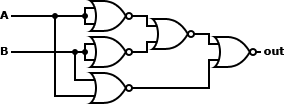
A ⊕ B ≡ ((A ↓ A) ↓ (B ↓ B)) ↓ (A ↓ B) |
 |
| NAND |
A ↑ B ≡ ((A ↓ A) ↓ (B ↓ B)) ↓ ((A ↓ A) ↓ (B ↓ B)) |
 |
| NOR |
A ↓ B ≡ A ↓ B |
 |
| XNOR |
A ↔ B ≡ (((A ↓ A) ↓ (B ↓ B)) ↓ (A ↓ B)) ↓ (((A ↓ A) ↓ (B ↓ B)) ↓ (A ↓ B)) |
 |
8.1.2. NAND
| Gate |
Logic |
Circuit |
| NOT |
¬A ≡ A ↑ A |
 |
| AND |
A ∧ B ≡ (A ↑ B) ↑ (A ↑ B) |
 |
| OR |
A ∨ B ≡ (A ↑ A) ↑ (B ↑ B) |
 |
| XOR |
A ⊕ B ≡ (A ↑ (A ↑ B)) ↑ (B ↑ (A ↑ B)) |
 |
| NAND |
A ↑ B ≡ A ↑ B |
 |
| NOR |
A ↓ B ≡ ((A ↑ A) ↑ (B ↑ B)) &uarr ((A ↑ A) ↑ (B ↑ B)) |
 |
| XNOR |
A ↔ B ≡ ((A ↑ (A ↑ B)) ↑ (B ↑ (A ↑ B))) ↑ ((A ↑ (A ↑ B)) ↑ (B ↑ (A ↑ B))) |
 |
8.2. Complex Circuits
8.2.1. Half Adder
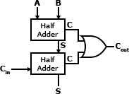
A half adder adds two one-bit binary numbers, A and B. The outputs are S and C (the value theoretically carried over to the next addition operation). The final summ is 2S + C. The half adder cannot be chained together because of the inability to use the carry from the last operation as an input.
Truth Table:
| INPUT |
OUTPUT |
| A |
B |
S |
C |
| F |
F |
F |
F |
| F |
T |
T |
F |
| T |
F |
T |
F |
| T |
T |
F |
T |
Circuit:

Example:
A full adder created using half adders:
8.2.2. Full Adder
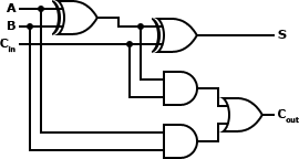
A full adder operates in the same way a half adder does. However, because the full adder takes a carry value (Cin) as input a full adder may be chained together to create an adder for a larger number.
Truth Table:
| INPUT |
OUTPUT |
| A |
B |
Cin |
S |
Cout |
| F |
F |
F |
F |
F |
| F |
F |
T |
T |
F |
| F |
T |
F |
T |
F |
| F |
T |
T |
F |
T |
| T |
F |
F |
T |
F |
| T |
F |
T |
F |
T |
| T |
T |
F |
F |
T |
| T |
T |
T |
T |
T |
Circuit:
Example:
A 4-bit adder created using full adders:

8.2.3. Decoder
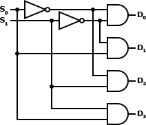
A decoder reverses the operation of an encoder. The original data is reconstituted from the encoded data into its original form. A decoder is commonly used to create a multiplexer and demultiplexer.
Truth Table:
| INPUT |
OUTPUT |
| S0 |
S1 |
D3 |
D2 |
D1 |
D0 |
| F |
F |
F |
F |
F |
T |
| F |
T |
F |
F |
T |
F |
| T |
F |
F |
T |
F |
F |
| T |
T |
T |
F |
F |
F |
Circuit:
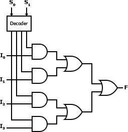
8.2.4. Multiplexer
A multiplexer is used to combine multiple streams of data into a single stream. The resultant data stream is split back into its original data streams using a demultiplexer.
Truth Table:
| INPUT |
OUTPUT |
| S1 |
S0 |
I3 |
I2 |
I1 |
I0 |
F |
| F |
F |
F |
F |
F |
F |
F |
| F |
F |
F |
F |
F |
T |
T |
| F |
F |
F |
F |
T |
F |
F |
| F |
F |
F |
F |
T |
T |
T |
| F |
F |
F |
T |
F |
F |
F |
| F |
F |
F |
T |
F |
T |
T |
| F |
F |
F |
T |
T |
F |
F |
| F |
F |
F |
T |
T |
T |
T |
| F |
F |
T |
F |
F |
F |
F |
| F |
F |
T |
F |
F |
T |
T |
| F |
F |
T |
F |
T |
F |
F |
| F |
F |
T |
F |
T |
T |
T |
| F |
F |
T |
T |
F |
F |
F |
| F |
F |
T |
T |
F |
T |
T |
| F |
F |
T |
T |
T |
F |
F |
| F |
F |
T |
T |
T |
T |
T |
| F |
T |
F |
F |
F |
F |
F |
| F |
T |
F |
F |
F |
T |
F |
| F |
T |
F |
F |
T |
F |
T |
| F |
T |
F |
F |
T |
T |
T |
| F |
T |
F |
T |
F |
F |
F |
| F |
T |
F |
T |
F |
T |
F |
| F |
T |
F |
T |
T |
F |
T |
| F |
T |
F |
T |
T |
T |
T |
| F |
T |
T |
F |
F |
F |
F |
| F |
T |
T |
F |
F |
T |
F |
| F |
T |
T |
F |
T |
F |
T |
| F |
T |
T |
F |
T |
T |
T |
| F |
T |
T |
T |
F |
F |
F |
| F |
T |
T |
T |
F |
T |
F |
| F |
T |
T |
T |
T |
F |
T |
| F |
T |
T |
T |
T |
T |
T |
| T |
F |
F |
F |
F |
F |
F |
| T |
F |
F |
F |
F |
T |
F |
| T |
F |
F |
F |
T |
F |
F |
| T |
F |
F |
F |
T |
T |
F |
| T |
F |
F |
T |
F |
F |
T |
| T |
F |
F |
T |
F |
T |
T |
| T |
F |
F |
T |
T |
F |
T |
| T |
F |
F |
T |
T |
T |
T |
| T |
F |
T |
F |
F |
F |
F |
| T |
F |
T |
F |
F |
T |
F |
| T |
F |
T |
F |
T |
F |
F |
| T |
F |
T |
F |
T |
T |
F |
| T |
F |
T |
T |
F |
F |
T |
| T |
F |
T |
T |
F |
T |
T |
| T |
F |
T |
T |
T |
F |
T |
| T |
F |
T |
T |
T |
T |
T |
| T |
T |
F |
F |
F |
F |
F |
| T |
T |
F |
F |
F |
T |
F |
| T |
T |
F |
F |
T |
F |
F |
| T |
T |
F |
F |
T |
T |
F |
| T |
T |
F |
T |
F |
F |
F |
| T |
T |
F |
T |
F |
T |
F |
| T |
T |
F |
T |
T |
F |
F |
| T |
T |
F |
T |
T |
T |
F |
| T |
T |
T |
F |
F |
F |
T |
| T |
T |
T |
F |
F |
T |
T |
| T |
T |
T |
F |
T |
F |
T |
| T |
T |
T |
F |
T |
T |
T |
| T |
T |
T |
T |
F |
F |
T |
| T |
T |
T |
T |
F |
T |
T |
| T |
T |
T |
T |
T |
F |
T |
| T |
T |
T |
T |
T |
T |
T |
Circuit:
8.2.5. Demultiplexer
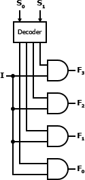
A demultiplexer splits a data stream that was combined using a multiplexer back into its original composite data streams.
Truth Table:
| INPUT |
OUTPUT |
| S1 |
S0 |
I |
F3 |
F2 |
F1 |
F0 |
| F |
F |
F |
F |
F |
F |
F |
| F |
F |
T |
F |
F |
F |
T |
| F |
T |
F |
F |
F |
F |
F |
| F |
T |
T |
F |
F |
T |
F |
| T |
F |
F |
F |
F |
F |
F |
| T |
F |
T |
F |
T |
F |
F |
| T |
T |
F |
F |
F |
F |
F |
| T |
T |
T |
T |
F |
F |
F |
Circuit:
|
